Feel free to give us feedback on which tutorial you would like to see next. You can also create a product in a material that is not supported by your 3D printer.
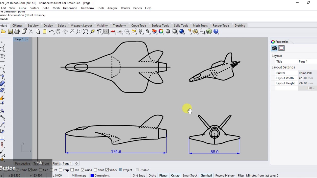
Rhino 6 Making 2d Drawings From 3d Model Drawing Book Pdf Drawings Technical Drawing
The output is the Flow Accumulation Grid having a default name of Fac that can be overwritten.

. The concept of optical flow was introduced by the American psychologist James J. Computer Arts offers daily design challenges with invaluable insights and brings you up-to-date on the latest trends styles and techniques. The Flow screen eases your way into FM synthesis with a uniquely designed graphic FM modulation matrix that connects four powerful monopolyphonic oscillators with independent waveform and pan controls.
Confirm that the input of the Flow Direction Grid is Fdr. Close Log In. Remember me on this computer.
Hi I am using a 100k glass bead thermistor meant for 3d printing and wired it up like you showed and uploaded the code. Complete this section and become an Excel pro. Log in with Facebook Log in with Google.
When i visit the serial monitor the temperature given there is negative and makes no sense whatsoever. Please tell me what is happening. The examples and features on this page can also be found on the right side of each chapter.
Working time will vary depending on a number of factors. Enter the email address you signed up with and well email you a reset link. Upon successful completion of the process the flow accumulation grid Fac is added to the map.
We are also publishing tutorials with tips tricks of the trade. Arc Hydro Tools v20 Tutorial October 2011 2 Set Flow Direction Drainage Boundary Definition The following tables summarize the requirements ArcEditorArcInfo and Spatial Analyst for each function in Arc Hydro. If SolidWorks Flow Simulation is not in the list you need to install SolidWorks Flow Simulation first.
1 Click Tools Add-Ins. Feel free to ask anything on our forums or on our 3Dflow Academy Facebook Group Free 3DF Zephyr manual. You can get up running in few minutes and create your first 3D reconstruction with few clicks.
Introduction to AutoCAD Plant 3D 2016. In this How To we will show you some of the best practices associated with creating silicone molds around 3D printed parts. If SolidWorks Flow Simulation is properly installed the Flow Simulation menu appears on the SolidWorks menu bar.
Terrain Preprocessing Requires ArcInfoArcEditor Requires Spatial Analyst Level DEM x DEM Reconditioning x Assign Stream Slope Burn Stream Slope x Build Walls x. The Add-Ins dialog box appears. 2 Check the checkboxes next to SolidWorks Flow Simulation.
Creating a mold around our 3D printed part took us about 15 hours. Flow Motion combines the best elements of FM frequency modulation and analog-style subtractive synthesis in one powerful instrument. Optical flow can also be defined as the distribution of apparent velocities of movement of brightness pattern in an image.
We encourage questions and dicussions. On the ArcHydro toolbar select Terrain Preprocessing Flow Accumulation. Optical flow or optic flow is the pattern of apparent motion of objects surfaces and edges in a visual scene caused by the relative motion between an observer and a scene.

Material Design Of Robinson The Journey Substance Designer Tutorial Robinson The Journey Material Design
Solidworks Flow Simulation Pdf Book Solidworks Pdf Books Free Ebooks Download

Pin On Zbrushing

Artstation Matthias Schmidt Video Game Artist Design Schmidt

Mograph Forming With Particle Flow Box2 And Box3 3ds Max Tutorial 3d Model

Pin On Autocad

Mograph Real Flow Thinking Particles Cinema 4d Tutorial Cinema 4d Tutorial Cinema 4d Cinema

Arena Simulation Of Complex Garment Assembly Line Mechanical Projects Assembly Line Simulation
0 comments
Post a Comment